Raul Fattore
November 7, 2024
Table of Contents
Summary
Relative motion depends on relative coordinates, not reference frames, and the same motion results will be measured in any frame of reference. Einstein’s unfortunate theory has led to the loss of over 100 years of evolution in physics. A comprehensive spatial power radiation equation has been obtained from the total energy of a system of charges, containing jitter terms. The Universal Electrodynamic Force is the base of these equations, valid on any scale. The derived equation proves the Cherenkov effect and demonstrates the real radiation pattern from the relative motion of charges for typical motions. The widely published equation of radiation’s “searchlight” effect is not compatible with the Cherenkov effect.
Abstract
Charge radiation has been the subject of several scientific articles, the majority of which draw from Larmor’s vast writings [1] and more recent efforts that have incorporated concepts from Einstein’s ill-fated theory of relativity. However, there may be misinterpretations when discussing the radiation power patterns for specific common charge motions.
The radiation from moving charges is derived from the Liénard-Wiechert potentials in most scientific works by introducing an arbitrary unit vector that points to the observer’s frame of reference, which is at an arbitrary angle to the direction of motion.
This indicates that the radiation power patterns obtained in this way are the patterns that an observer in a different frame would apparently see with respect to the charge, rather than the real charge radiation pattern that arises from the motion.
- Does charge radiation field depend on a reference frame?
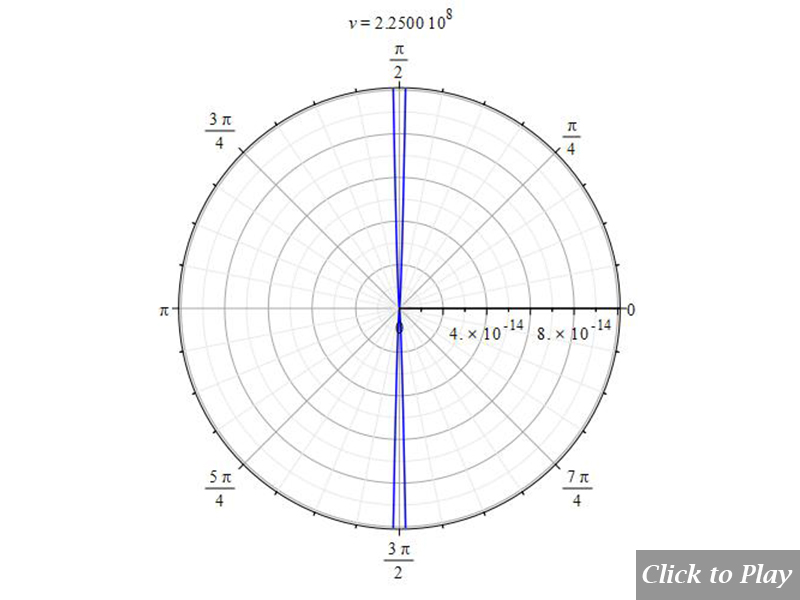
- What is the real radiation power pattern of a moving charge?
- What type of motion produces the “search light” effect of radiation?
- What happens with the radiation field in non-linear motion?
- Is there a charge radiation equation that also proves the Cherenkov effect?
In this study, you’ll find the answers to the above questions, which are backed by the experimentally proven laws of electrodynamics through the Universal Electrodynamic Force.
Introduction
This work presents a charge radiation power equation that is obtained from the Universal Electrodynamic Force [2]. The Universal Force, in turn, is derived from the fundamental empirical equations of electrodynamics, which are solved simultaneously by the method of substitution using the Galilean transformation.
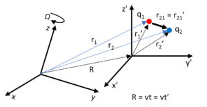
Relative motion only depends on relative coordinates
The Universal Electrodynamic Force, which is based on the relative motion of two charges, is entirely relational, and whatever we measure from this motion will have the same value in all frames of reference.
It is a real relativistic theory because it only depends on relative coordinates instead of relative reference frames.
From this Universal Force, one can derive many equations, for example, forces that are superior to Newton’s second law and Newton’s gravitational law, the centrifugal force, the equation of mass, all electrostatic and electrodynamic laws, the radiation, radiation reaction forces, and more.
The Universal Force is not an action-at-a-distance force. It is based on finite size, elastic particles, and self-fields, uses Galilean transformation based on causality, always conserves energy and momentum, satisfies Mach’s principle and has chiral symmetry. Furthermore, it is really relativistic because it only depends on relative coordinates instead of relative reference frames.
As the Universal Force is valid on any scale, it can clearly explain atomic and nuclear interactions, as well as interactions among celestial bodies or galaxies. You’ll find some more details on the Universal Electrodynamic Force in the article Negative Mass and Negative Refractive Index in Atom Nuclei – Nuclear Wave Equation – Gravitational and Inertial Control -(Part 1)-.
The Universal Electrodynamic Force
Lucas’ universal electrodynamic force in vectorial form is:

(1)
Where \vec{\beta}=\frac{\vec{v}}{c}, and \vec{r},\ \vec{v},\ \vec{a}, are the relative position, velocity, and acceleration between the two charges.
In general, velocity and acceleration may not have the same direction. Let’s define their angles with respect to the vector \vec{r}.
\theta: angle between \vec{r} and \vec{v}
\alpha: angle between \vec{r} and \vec{a}
Then, we can write the universal force in geometrical form:

(2)
The Charge Radiation Force
A brief analysis of the terms of the Universal Force [3] can be read in the article on Nuclear Fusion Enhanced by Negative Mass – A Proposed Method and Device – (Part 1), where an equation of the radiation force has been obtained, which demonstrates the radiation for linear and non-linear accelerated motion like Bremsstrahlung, which also includes synchrotron radiation, cyclotron radiation, etc. The radiation force resulted in the following equation:
{\vec{F}}_{rad}=\frac{q_1q_2}{4\pi\varepsilon_0r^2c^2\left(1-\beta^2\cdot\sin^2{\left(\theta\right)}\right)^\frac{3}{2}}\cdot\left(-\frac{rv}{c^2}\left(2\sin^2{\left(\theta\right)}+1\right)v\vec{a}+3r\vec{a}-a\cos{\left(\alpha\right)}r\hat{r}+\frac{rv}{c^2}\cos{\left(\alpha\right)}va\hat{r}\right) (3)
This radiation force is made up of the two radiation terms of the Universal Force that make it valid for any type of motion. However, even when this force gives us a very good approximation of charge radiation, it is partially disregarding the energy of the system, as it doesn’t include the remaining terms of the Universal Electrodynamic Force.
The Total Energy of a System of Charges
There is no reason for the laws of electrodynamics not to be valid at atomic scales. There is no such thing as “Nuclear Strong Force” or “Nuclear Weak Force.” There is only one force in Mother Nature that is valid on any scale: the Universal Electrodynamic Force. It can clearly explain atomic and nuclear interactions without any need to create any new forces, as Quantum Theory did.
The Total Energy [4] of moving charges is derived from the Universal Electrodynamic Force, which gives us an accurate energy equation. You can find more details in the article Nuclear Fusion Enhanced by Negative Mass – A Proposed Method and Device – (Part 2).
The Total Energy equation has three terms:
1) The Potential Energy term, which depends on the relative position of the charges.
2) One Kinetic Energy term, which depends on the relative velocity of the charges.
3) One Kinetic Energy term, which depends on the relative acceleration of the charges. This term accounts for radiation energy and is not found in the scientific literature as being part of the total energy of the system.
E=\frac{1}{\sqrt{1+\left(\cos^2{\left(\theta\right)}-1\right)\frac{v^2}{c^2}}}\cdot\left(kq_1q_2\cdot\left(\frac{1}{r_f}-\frac{1}{r_i}\right)-\frac{kq_1q_2}{c^2}\cdot\left(\frac{1}{r_f}-\frac{1}{r_i}\right)\cdot v^2-\frac{2kq_1q_2\cos{\left(\alpha\right)}}{c^2}\cdot\left(\ln{\left(r_i\right)}-\ln{\left(r_f\right)}\right)\cdot a\right) (4)
Where E is the total energy of the system, r_i and r_f are the initial and final distance between the charge centers.
The initial distance is usually taken such that the rest energy of the system is approximately zero, which usually means r=\infty. But as infinity is not a defined number, let’s take a practical value from Mother Nature that can realistically be used instead. Infinity can be replaced by a huge distance, approx. x10 bigger than the oldest light we have observed from the “Big Bang” ({46500\ 10}^6ly={4.410}^{26}m). To go safe, we’ll take r_i={10}^{27}m.
As we can see in Eq. (4), the total energy is affected by a factor \gamma_E=\frac{1}{\sqrt{1+\left(\cos^2{\left(\theta\right)}-1\right)\frac{v^2}{c^2}}} that is physically realistic compared to the known “Lorentz factor”, because it also takes into account the type of motion that is given by the angle \theta between \vec{r} and \vec{v} (the relative position and velocity). Note that the “Lorentz factor” is only valid for circular motion. Also note that 1\le\gamma_E\le\infty depending on the angle \theta between \vec{r} and \vec{v} and the relative velocity, reaching a maximum value (or \infty) for \theta=\frac{\pi}{2}.
We can write the total energy of the system in short form as:
E=\gamma_E\left(U+K+E_{rad}\right) (5)
The “rest energy” is no other than the potential energy “U” when the kinetic variables are zero (v=0 and a=0). The Universal Force shows us that velocity zero doesn’t mean that acceleration should be zero. Note that in this case \gamma_E=1. Under such conditions, the rest energy is:
E=E_0=UThe “rest energy” depends on the distance between the centers of charges.
We successfully applied the Total Energy equation, among other things, to precisely calculate the real released energy in nuclear fusion [5] and the single energy of the products, including radiation. For more details, read the article Nuclear Fusion Enhanced by Negative Mass – A Proposed Method and Device – (Part 3).
The Cherenkov Effect
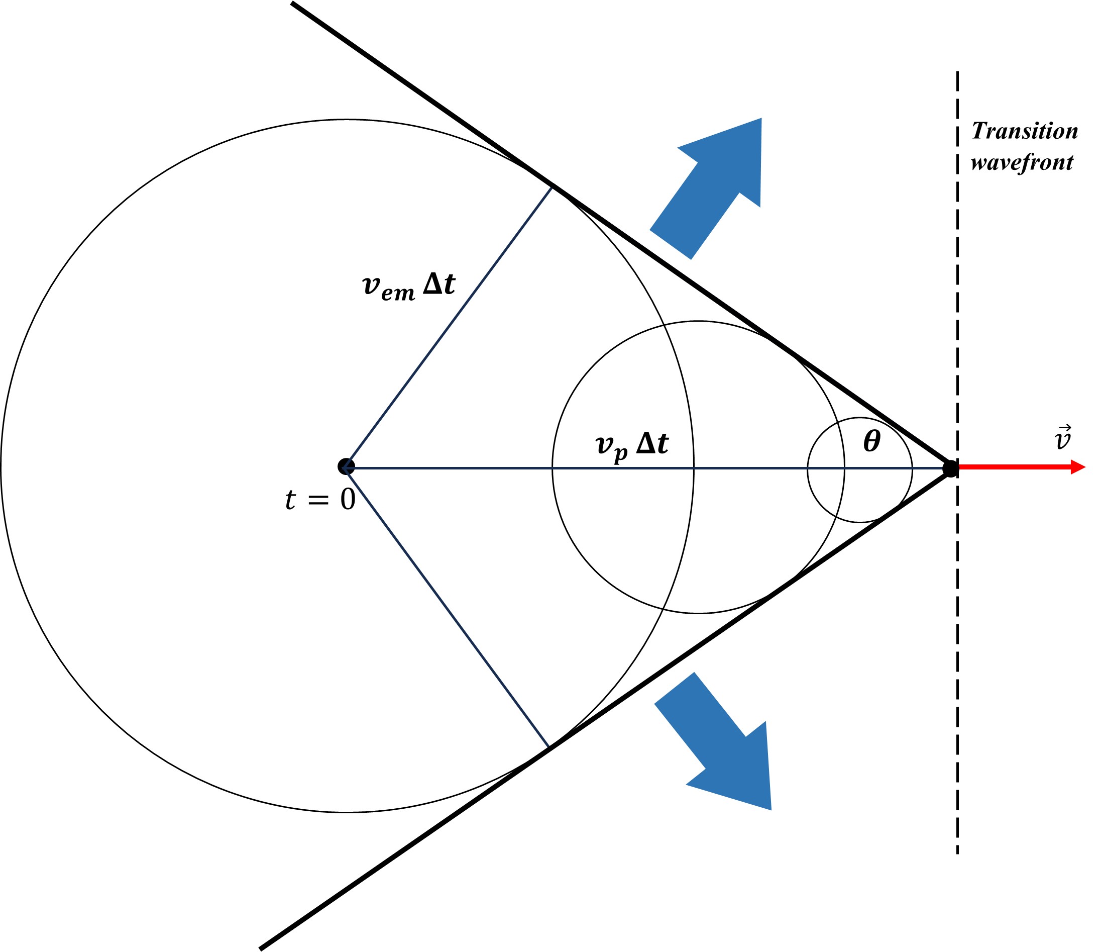
When a charge moves in a medium with a higher velocity than the propagation velocity of the electromagnetic radiation (phase velocity), then electromagnetic shock waves are produced.
The Cherenkov effect caused by a charge
These shock fields (or waves) start when the charge velocity is infinitesimally higher than the radiation velocity.
At the transition velocity, the wavefront in front of the charge moves perpendicular to the motion direction (see Fig. 1a). As soon as the transition velocity occurs, the wavefront experiments an abrupt angle change from \frac{\pi}{2} to (\pi-\theta), which is now the shock wave’s wavefront.
The pattern must follow the radiation’s evolution and reduce the aperture angle behind the charge until it reaches the lowest aperture, which is determined by the medium’s properties and the charge velocity.
The velocity of the electromagnetic wavefront in the medium is: v_{em}=\frac{c}{n}, where n is the index of refraction. The distance traveled by the wavefront from t=0 to t=∆t is v_{em}∆t.
For the same time interval, the particle covered the distance v_p∆t. We also define \beta=\frac{v_p}{c}.
The aperture angle of the wavefront with respect to the velocity axis is:
\sin{\left(\theta\right)}=\frac{v_{em}}{v_p}=\frac{\frac{c}{n}}{\beta c}=\frac{1}{n\beta} (5a)
This equation gives a minimum charge velocity for the radiation, under which the arcsin(\frac{1}{n\beta})>1. This limit is exactly \beta=\frac{1}{n}.
The higher the charge velocity, the smaller the wavefront aperture.
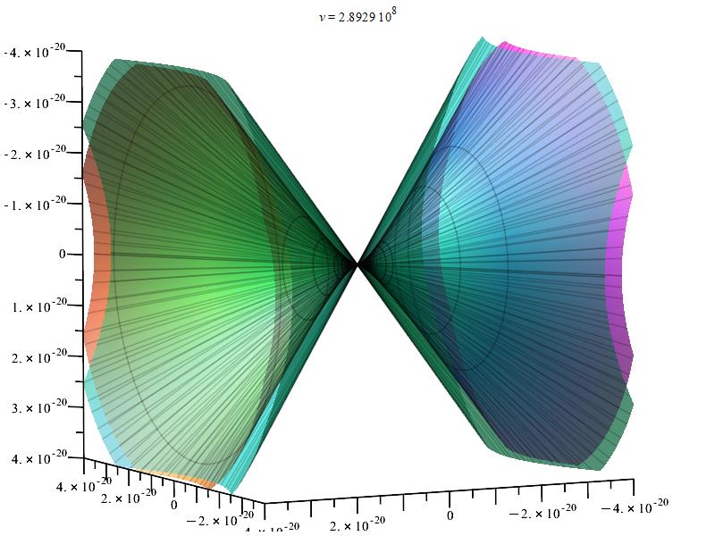
3D polar graph showing an example of the Cherenkov radiation by a charge moving in accelerated linear motion
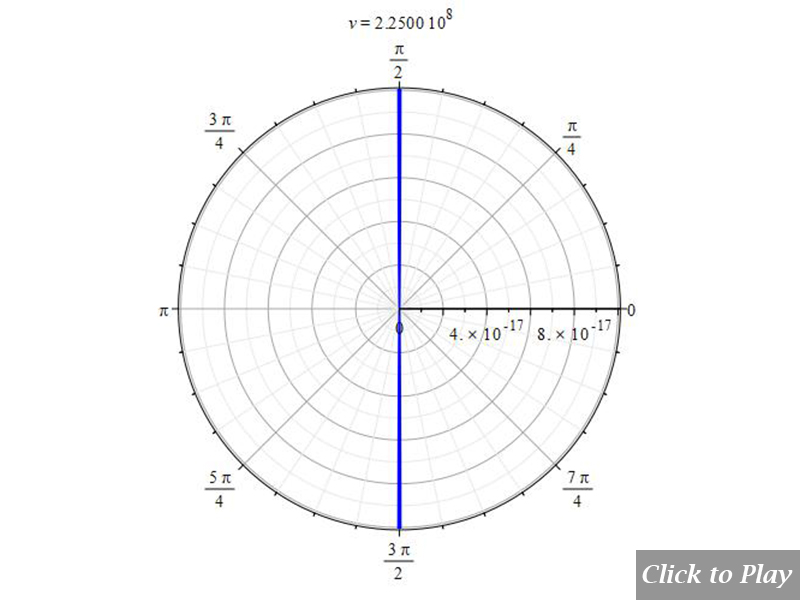
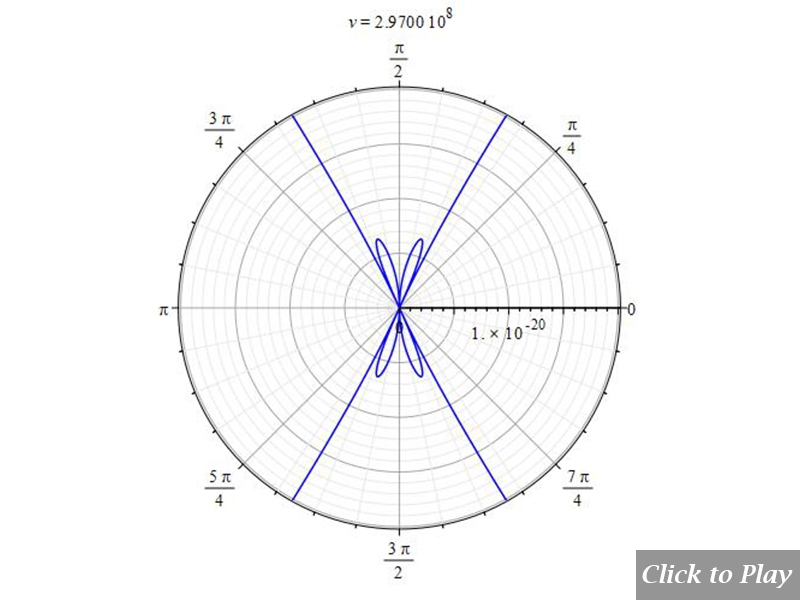
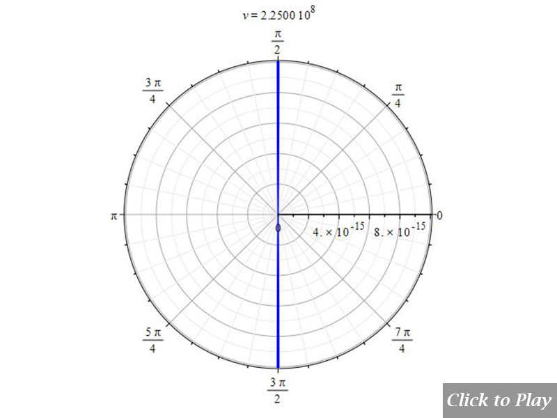
In our graphs of the Cherenkov effect, we’ll consider the medium as water, with an index of refraction n=1.33, and set the speed of light in the equation accordingly, i.e., c=2.25\ {10}^8\ [\frac{m}{s}].
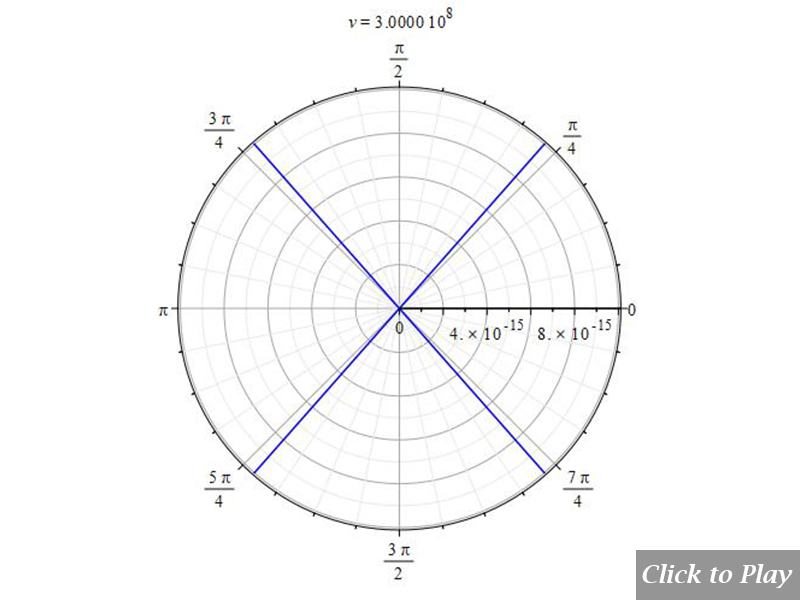
To better see the effect and how the radiation pattern evolves, we’ll start from a charge velocity below the shock threshold and increase it to the maximum, i.e., v_p=3\ {10}^8\ [\frac{m}{s}]. For this maximum charge velocity, the 2D polar graphs show that the minimum aperture angle of the shock wave wavefront in water is 48.6°, which is compatible with equation (5a).
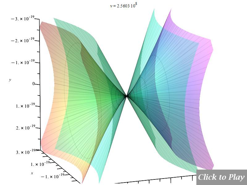
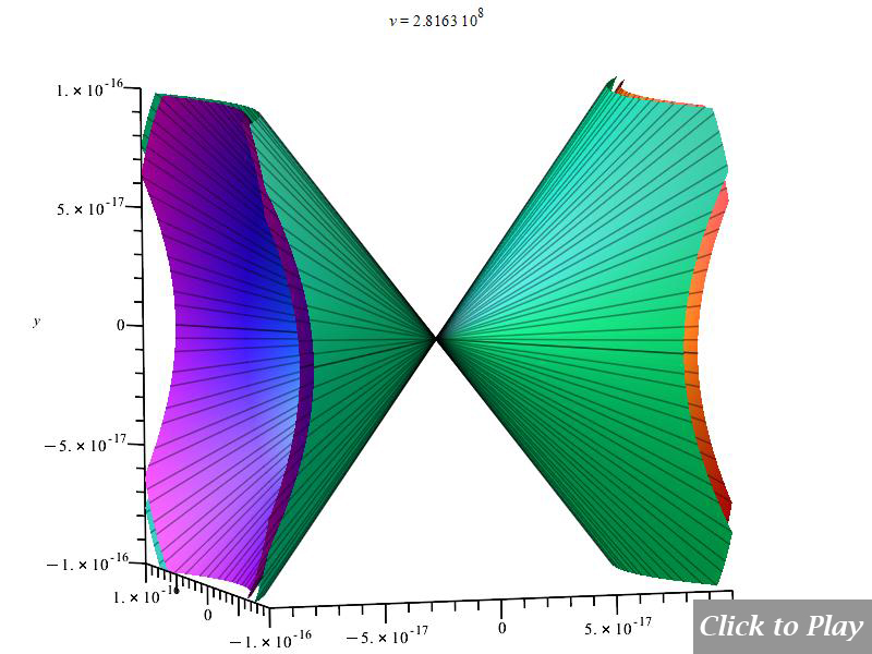
Keep in mind that in 3D Cherenkov effect graphs, the external cone envelope gives the wavefront of the shock waves.
In non-linear motion, the wavefront of the shock wave does not follow the straight-line aperture seen in Fig. 1a. Nonetheless, we use a relative distance between the charges in all of our graphs, which results in a relatively low wave propagation time for that distance. In all of our scenarios, we can thus assume with a fairly acceptable approximation that the wavefront of the shock wave follows a straight line.
Charge Radiation – Calculation of the Radiation Power
The Total Energy equation (4) of the system of charges can now be applied for the calculation of the radiation power of moving charges.
Power is defined as the time derivative of the energy P=\frac{dE}{dt}. We are interested in finding the spatial distribution of power per unit area. The rate of energy per unit area is the intensity: I=\frac{1}{A}\ \frac{dE}{dt}\ [\frac{W}{m^2}]. The area described by a solid angle is dA={r(t)}^2\ d\Omega. Replacing this in the intensity equation: I=\frac{P}{{r(t)}^2\ d\Omega}. As the power radiated per solid angle is {dP}_{sr}=\frac{P}{d\Omega}, we can replace this in the previous equation: I=\frac{{dP}_{sr}}{{r(t)}^2}.
Then, the power radiated per solid angle becomes {dP}_{sr}={r(t)}^2\ I\ \ [\frac{W}{sr}]. Now consider that we ”wrap” the charge inside a sphere where the radiation is isotropically distributed on its surface. The intensity at the surface of a sphere of radius r\left(t\right) is I=\frac{P}{4\ \pi\ {r(t)}^2}. Replacing this in the previous equation: {dP}_{sr}={r(t)}^2\ \frac{P}{4\ \pi\ {r(t)}^2}\ [\frac{W}{sr}]. That is, our final calculation of the power per solid angle reduces to:
{dP}_{sr}=\frac{1}{4\pi}\ \frac{dE}{dt} (6)
We can safely assume that \alpha=\theta=constant for the short interval dt, and take the time derivative of Eq. (4), which results in our general equation of the power radiated per solid angle:
dP_{sr}=\frac{kq_1q_2}{4\pi}\left(-\frac{\left(\frac{1}{r\left(t\right)}-\frac{{\dot{r}\left(t\right)}^2}{r\left(t\right)c^2}-\frac{2\cos{\left(\alpha\right)}\left(62.17-\ln{\left(r\left(t\right)\right)}\right)\ddot{r}\left(t\right)}{c^2}\right)\left(\cos^2{\left(\theta\right)}-1\right)\dot{r}\left(t\right)\ddot{r}\left(t\right)}{\left(1+\frac{{\left(\cos^2{\left(\theta\right)}-1\right)\dot{r}\left(t\right)}^2}{c^2}\right)^\frac{3}{2}c^2}+\frac{-\frac{\dot{r}\left(t\right)}{r\left(t\right)^2}+\frac{{\dot{r}\left(t\right)}^3}{r\left(t\right)^2c^2}-\frac{2\dot{r}\left(t\right)\ddot{r}\left(t\right)}{r\left(t\right)c^2}+\frac{2\cos{\left(\alpha\right)}\dot{r}\left(t\right)\ddot{r}\left(t\right)}{c^2r\left(t\right)}-\frac{2\cos{\left(\alpha\right)}\left(62.17-\ln{\left(r\left(t\right)\right)}\right)\ \frac{d}{dt}\left(\ddot{r}\left(t\right)\right)}{c^2}}{\sqrt{1+\frac{{\left(\cos^2{\left(\theta\right)}-1\right)\dot{r}\left(t\right)}^2}{c^2}}}\right) (7)
Note that the radiated power contains jitter in the last term, i.e., the time derivative of acceleration: j=\frac{d\vec{a}}{dt}. We may write Eq. (7) in a more visual way as follows:
dP_{sr}=\frac{kq_1q_2}{4\pi}\cdot\left(-\frac{\left(\frac{1}{\Vert\vec{r}\Vert}-\beta^2\frac{1}{\Vert\vec{r}\Vert}-\frac{2\cos{\left(\alpha\right)}\left(62.17-\ln{\left(\Vert\vec{r}\Vert\right)}\right)\Vert\vec{a}\Vert}{c^2}\right)\left(\cos^2{\left(\theta\right)}-1\right)\Vert\vec{v}\Vert\Vert\vec{a}\Vert}{\left(1+\beta^2\left(\cos^2{\left(\theta\right)}-1\right)\right)^\frac{3}{2}c^2}+\frac{-\frac{\Vert\vec{v}\Vert}{\Vert\vec{r}\Vert^2}+\beta^2\frac{\Vert\vec{v}\Vert}{\Vert\vec{r}\Vert^2}-\beta\frac{2\Vert\vec{a}\Vert}{\Vert\vec{r}\Vert c}+\beta\frac{2\cos{\left(\alpha\right)}\Vert\vec{a}\Vert}{\Vert\vec{r}\Vert\cdot c}-\frac{2\cos{\left(\alpha\right)}\left(62.17-\ln{\left(\Vert\vec{r}\Vert\right)}\right)\Vert\dot{\vec{a}}\Vert}{c^2}}{\sqrt{1+\beta^2\left(\cos^2{\left(\theta\right)}-1\right)}}\right) (8)
As we can see, the power radiated per solid angle is a non-linear differential equation, which might not be easy to solve, and I don’t have the time to do it now. In case you want to find the solution, I’ll much appreciate sharing it. I’ll be honored to publish it here in your name.
However, to have a general spatial power distribution, we can bound the power equation (8) with the equations of motion in spherical coordinates. As an alternative, by assigning the variables arbitrary values and creating “snapshots” at various relative distances, one would be able to find the power pattern for various motion types. By allowing velocity to vary within certain limits, these “snapshots” will be animated.
The total energy flow per unit time (power, P) radiated into all angles out of any closed surface is the integral over the surface:
P=\int\int{dP_{sr}}d\Omega=\int_{0}^{2\pi}{\int_{0}^{\pi}{dP_{sr}}\sin{\left(\theta\right)}d\theta}d\phiIn the following sections, we’ll make animated 2D and 3D polar graphs of the spatial distribution of the power radiated per solid angle (Eq. 8) for some types of motions. Graphs will be made for constant and variable acceleration (jitter) in the motion cases where applicable. Besides, the Cherenkov effect will be demonstrated in all types of motions.
Connecting spherical and polar coordinates’ polar angles
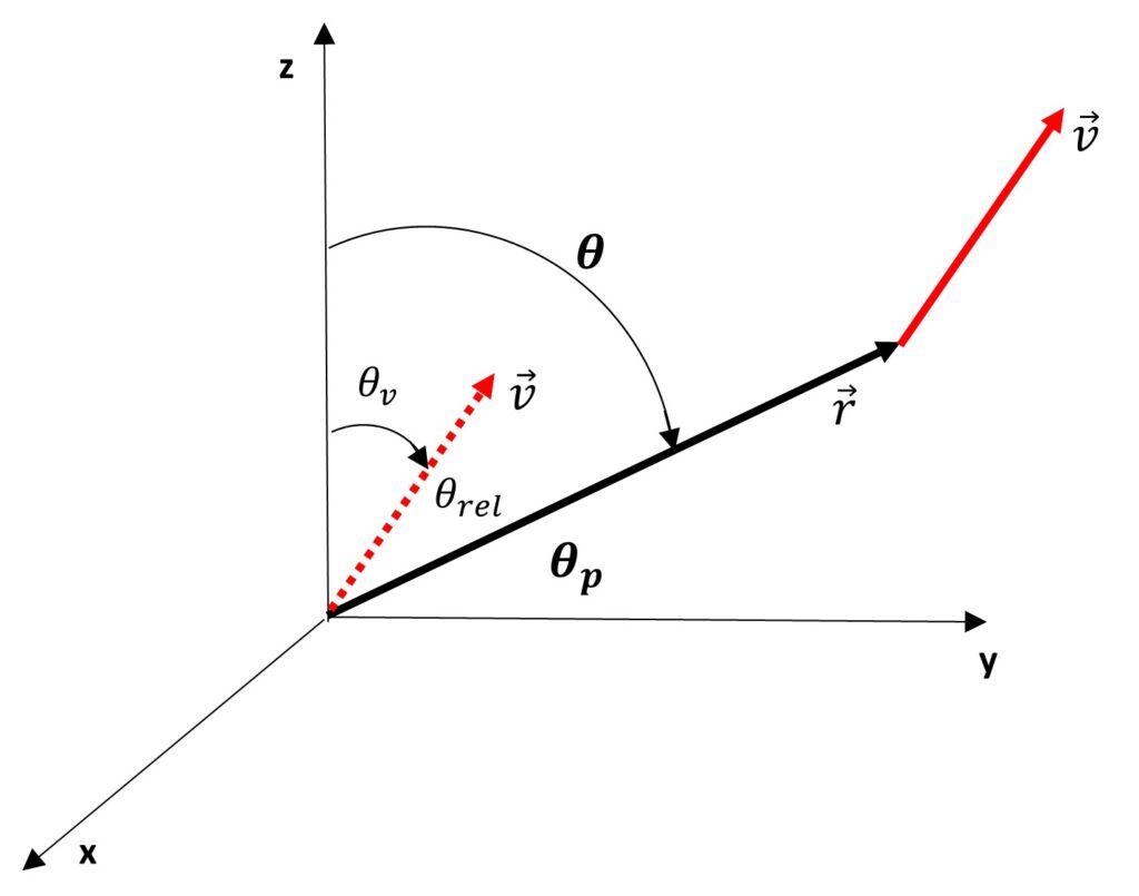
Angle shift for graphing the spherical coordinate radiation equation in polar coordinates
It is important to note that the angle \theta in Eq. (8) is the angle between \vec{v} and \vec{r} (\theta_{rel} in Fig. 2), and it is not to be confused with the polar angle of spherical coordinates (\theta in Fig. 2).
The angle \theta_p defined in polar coordinates is measured from a horizontal axis to the vector \vec{r}, while in spherical coordinates the angle is measured from the vertical axis.
Later, the relationship between the two angles will assist us in obtaining the appropriate polar graphs:
\theta_{rel}=\left(\theta-\theta_v\right) (9)
\theta_v=\frac{\pi}{2}-\left(\theta_p+\theta_{rel}\right) (10)
Replacing (10) in (9): \theta_p=(\frac{\pi}{2}-\theta) (11)
Relationship between velocity and acceleration angles
Generally speaking, acceleration and velocity might not go in the same direction. The following is how their angles in the equations are defined in relation to vector \vec{r}:
\theta: angle between \vec{r} and \vec{v}
\alpha: angle between \vec{r} and \vec{a}
By definition, we have:
\cos (\alpha)=\frac{{\vec{a}}\cdot {\vec{r}}}{{||{\vec{a}}||}\cdot {||{\vec{r}}||}} (11a)
\cos (\theta)=\frac{{\vec{v}}\cdot {\vec{r}}}{{||{\vec{v}}||}\cdot {||{\vec{r}}||}} (11b)
Dividing (11a) by (11b) and rearranging, we get:
\cos (\alpha)=\frac{{||{\vec{v}}||}\cdot ({\vec{a}}\cdot {\vec{r}})}{{||{\vec{a}}||}\cdot ({\vec{v}}\cdot {\vec{r}})}\cdot \cos (\theta) (11c)
We will generally have the following relationship between acceleration and velocity angles in order to produce polar plots with the proper symmetry:
\alpha (t)=\arccos \left(\frac{({\vec{a}}\cdot {\vec{r}})\cdot {||{\vec{v}}||}}{{||{\vec{a}}||}\cdot ({\vec{v}}\cdot {\vec{r}})}\cdot {\mid \cos (\theta (t))\mid}\right) (11d)
To get the right polar graph when velocity and acceleration are perpendicular to each other, it would be wise to add an angle shift of \frac{\pi}{2} to the cosine: {\mid \cos (\frac{\pi}{2}-\theta (t))\mid}.
Types of polar graphs made in this study
Because equation (8) is fully symmetrical, the polar graphs that are shown in this paper will be bidirectional, meaning that they will be specular for both positive and negative velocity. Unless stated otherwise, velocity will often be negative to the left of zero along the graph’s horizontal axis.
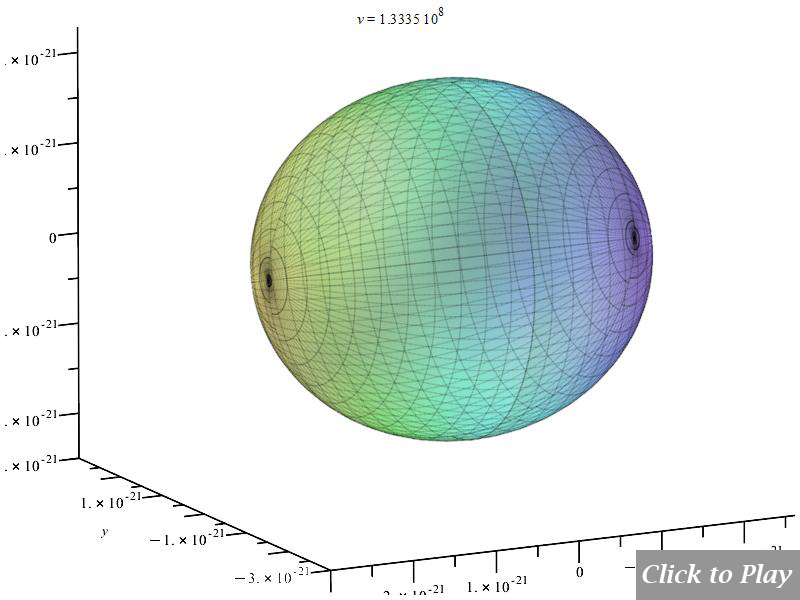
Figures 2a through 2d illustrate the appearance of unidirectional and bidirectional graphs in a linear and circular motion scenario.
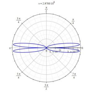
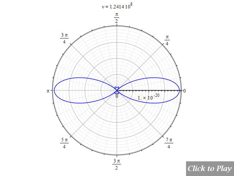
2D polar graph example showing a bidirectional plot of charge radiation power in linear motion
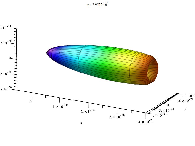
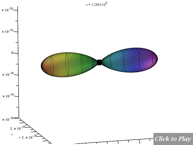
3D polar graph example showing a unidirectional plot of charge radiation power in linear motion
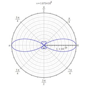
2D polar graph example showing a bidirectional plot of charge radiation power in circular motion
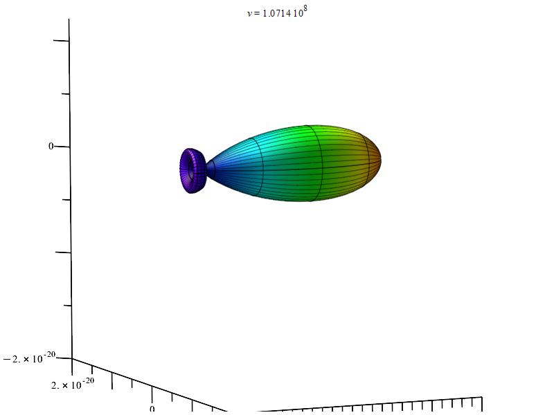
3D polar graph example showing a unidirectional plot of charge radiation power in circular motion
Charge Radiation in Linear Accelerated Motion
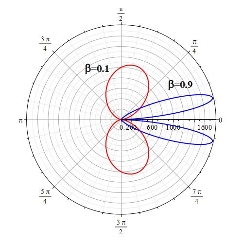
The “searchlight” effect of radiation given by Eq. (11e) is not compatible with the Cherenkov effect
In the scientific literature, one can read that the “searchlight” effect of radiation as the velocity increases happens when “the charge is accelerated in its direction of motion”, as shown, not in scale, in Fig. 3. The formula giving rise to this graph (it may vary slightly depending on the authors) is:
dP_{sr}=K\ a^2\frac{{\sin{\theta}}^2}{\left(1-\beta\ \cos{\theta}\right)^5} (11e)
Authors arrive at this formula by making corrections of the angles based on the relativistic aberration of light associated with the Lorentz transformation between two frames of reference.
Therefore, this has nothing to do with the real radiation of the charge resulting from the relative motion of the charges, which is independent of reference frames.
A significant proof that invalidates Eq. (11e) is that the radiation pattern does not obey the Cherenkov effect in linear accelerated motion, as will be demonstrated in the next section.
In contrast, the power emitted per solid angle, as determined by Eq. (8), satisfies the Cherenkov effect and predicts the “searchlight” effect in linear accelerated motion with perfect simultaneous symmetry in both velocity directions.
Given that Eq. (8) is derived from the Universal Electrodynamic Force, which is derived from the more than proven laws of electrodynamics, chances are that we might be right.
Polar graphs for radiation from charges in linear accelerated motion
The graphs are animated for a better visualization of the pattern as velocity increases. To have a general spatial power distribution, we can bound the power equation (8) with the equations of motion in spherical coordinates and replace the angle \alpha to eliminate it from the equation. In this motion \alpha=\theta=constant:
\vec{r}=r\left(t\right)\ \hat{r}\left(t\right) (12)
\vec{v}=\dot{\vec{r}} (13)
\vec{a}=\ddot{\vec{r}} (14)
\alpha =\arccos\left(\frac{{||{\vec{v}}||}\cdot ({\vec{a}}\cdot {\vec{r}})}{{||{\vec{a}}||}\cdot ({\vec{v}}\cdot {\vec{r}})}\cdot {\mid \cos (\theta (t))\mid}\right) (15)
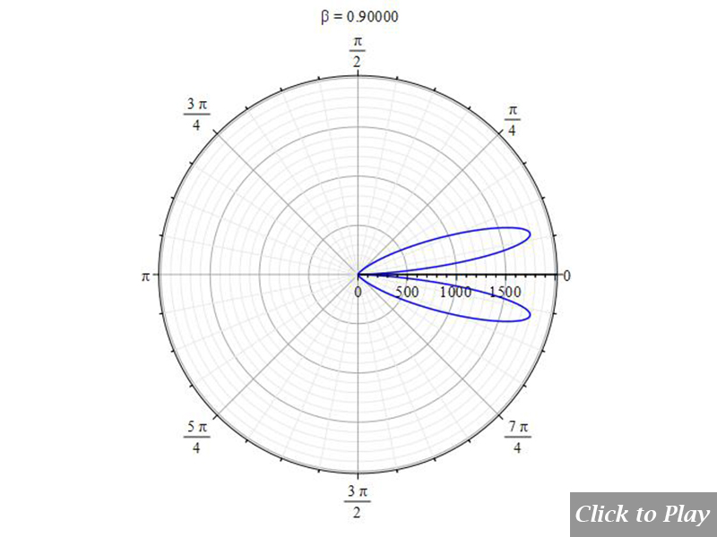
Equations of motion in spherical coordinates (12) to (14) and angle (15) are replaced in Eq. (8), and the following parameters were set for the polar graphs in Figs. 4 and 5:
| q_1=q_2={1.6\ 10}^{-19} | r\left(t\right)=see\ graphs | \dot{r}\left(t\right)=v | \ddot{r}\left(t\right)=5\:{10}^{15} |
| \dot{\theta}\left(t\right)=0 | \ddot{\theta}\left(t\right)=0 | \dot{\phi}\left(t\right)=0 | \ddot{\phi}\left(t\right)=0 |
| \frac{d}{dt}\left(\ddot{r}\left(t\right)\right)=0 | \frac{d}{dt}\left(\ddot{\theta}\left(t\right)\right)=0 | \frac{d}{dt}\left(\ddot{\phi}\left(t\right)\right)=0 |
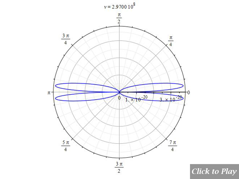
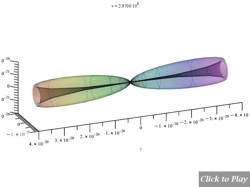
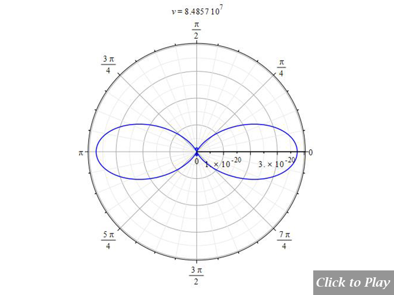
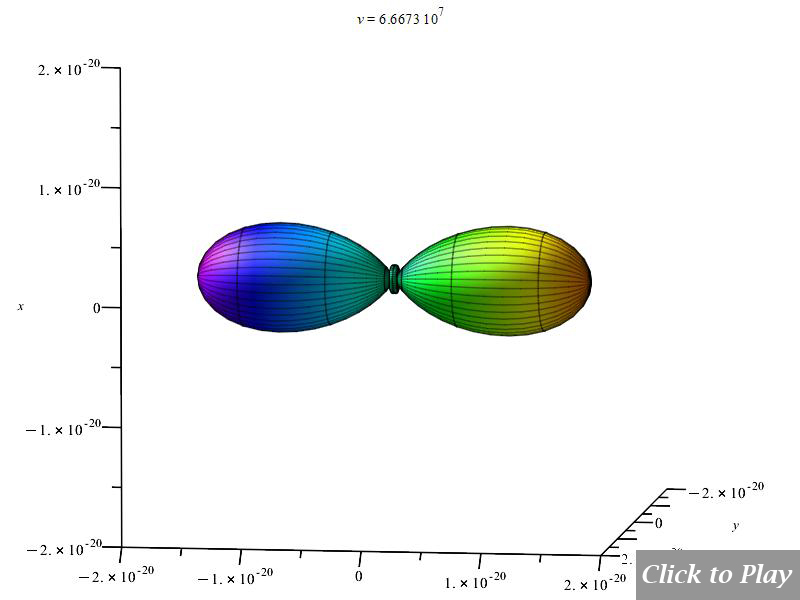
Velocity is on the horizontal axis. We see how the radiation pattern increases intensity as v\rightarrow\ c.
Equations of motion in spherical coordinates (12) to (14) and angle (15) are replaced in Eq. (8), and the following parameters were set for the polar graphs in Figs. 6 and 7:
| q_1=q_2={1.6\ 10}^{-19} | r\left(t\right)=see\ graphs | \dot{r}\left(t\right)=v | \ddot{r}\left(t\right)={10}^{15} |
| \dot{\theta}\left(t\right)=0 | \ddot{\theta}\left(t\right)=0 | \dot{\phi}\left(t\right)=0 | \ddot{\phi}\left(t\right)=0 |
| \frac{d}{dt}\left(\ddot{r}\left(t\right)\right)=0 | \frac{d}{dt}\left(\ddot{\theta}\left(t\right)\right)=0 | \frac{d}{dt}\left(\ddot{\phi}\left(t\right)\right)=0 |
In comparison to Figs. 4 and 5, Figures 6 and 7 display the radiation pattern at a little lower acceleration and a shorter distance between charges. At low velocity, the radiation field has a tendency to be spherical.
Example considering jitter in linear accelerated motion
Equations of motion in spherical coordinates (12) to (14) and angle (15) are replaced in Eq. (8), and the following parameters were set for the polar graphs in Figs. 8 and 9:
| q_1=q_2={1.6\ 10}^{-19} | r\left(t\right)=see\ graphs | \dot{r}\left(t\right)=v | \ddot{r}\left(t\right)=5\:{10}^{15} |
| \dot{\theta}\left(t\right)=0 | \ddot{\theta}\left(t\right)=0 | \dot{\phi}\left(t\right)=0 | \ddot{\phi}\left(t\right)=0 |
| \frac{d}{dt}\left(\ddot{r}\left(t\right)\right)={10}^{23} | \frac{d}{dt}\left(\ddot{\theta}\left(t\right)\right)=0 | \frac{d}{dt}\left(\ddot{\phi}\left(t\right)\right)=0 |
In general, jitter seems to enhance the radiation in all directions for a given acceleration.
The Cherenkov effect in linear accelerated motion
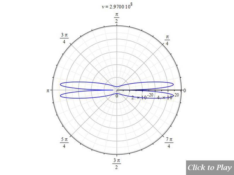
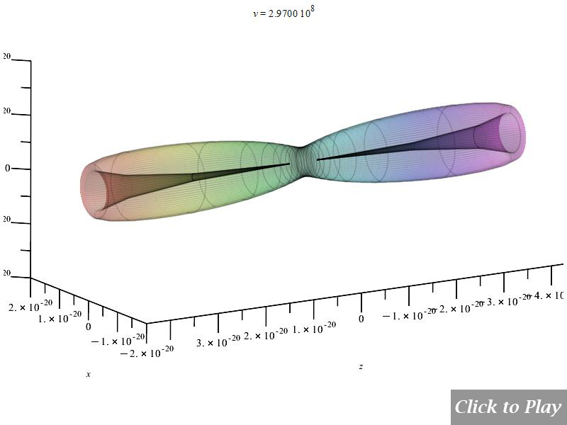
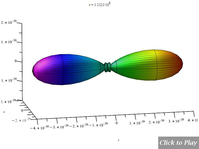
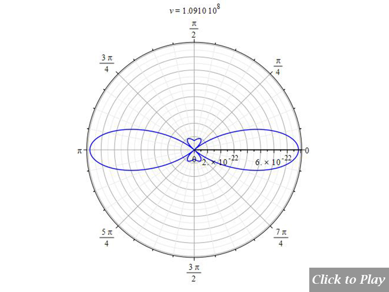
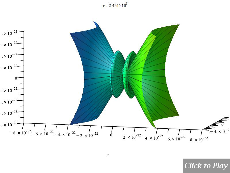
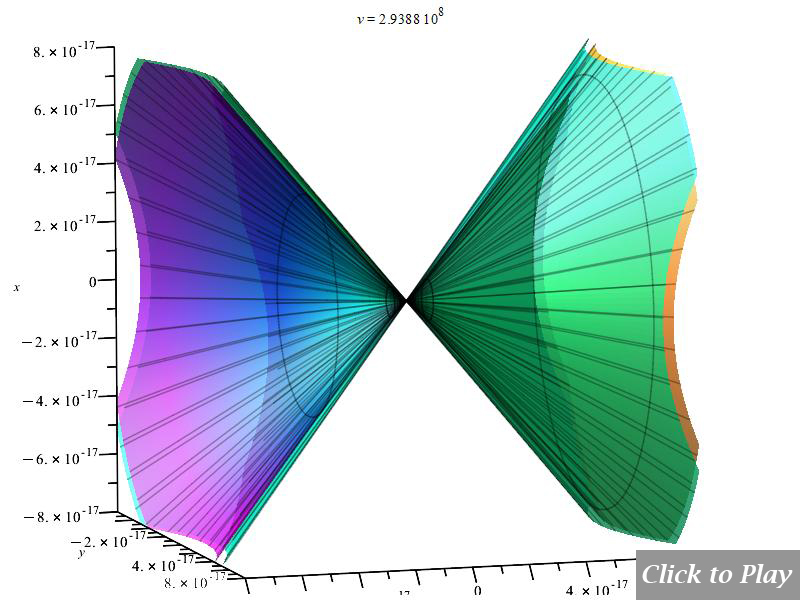
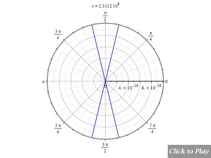
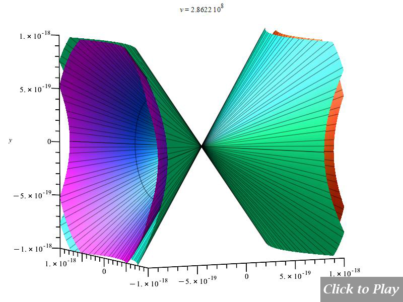
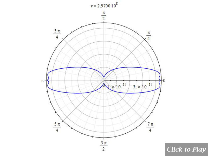
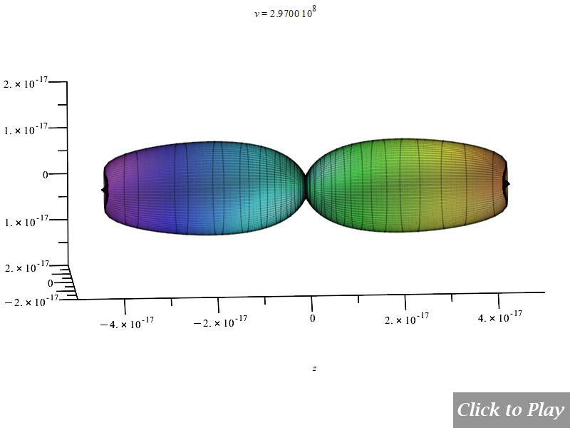
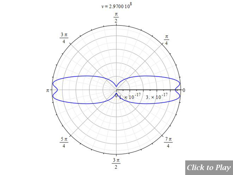
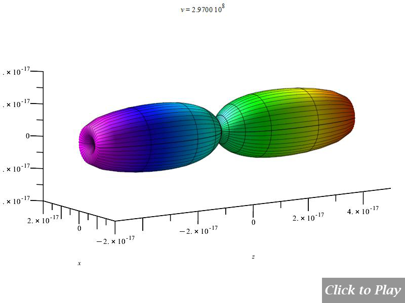
Equations of motion in spherical coordinates (12) to (14) and angle (15) are replaced in Eq. (8), and the following parameters were set for the polar graphs in Figs. 10 and 11:
| q_1=q_2={1.6\ 10}^{-19} | r\left(t\right)=see\ graphs | \dot{r}\left(t\right)=v | \ddot{r}\left(t\right)={5\ 10}^{15} |
| \dot{\theta}\left(t\right)=0 | \ddot{\theta}\left(t\right)=0 | \dot{\phi}\left(t\right)=0 | \ddot{\phi}\left(t\right)=0 |
| \frac{d}{dt}\left(\ddot{r}\left(t\right)\right)=0 | \frac{d}{dt}\left(\ddot{\theta}\left(t\right)\right)=0 | \frac{d}{dt}\left(\ddot{\phi}\left(t\right)\right)=0 | c=2.25\ {10}^8 |
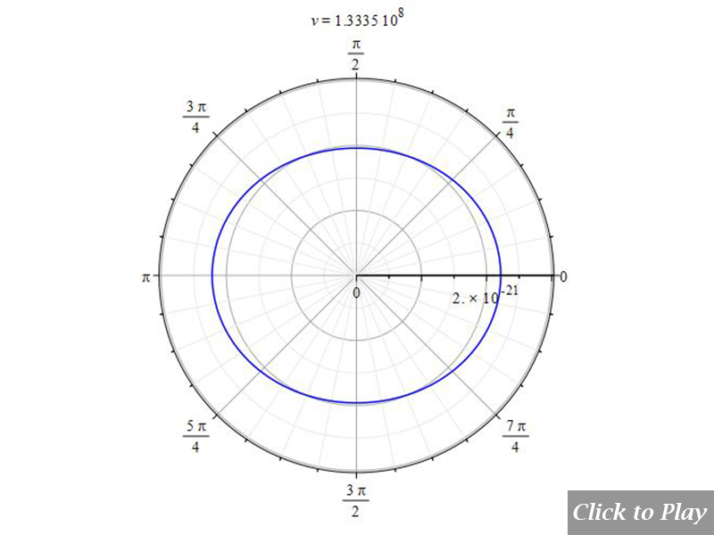
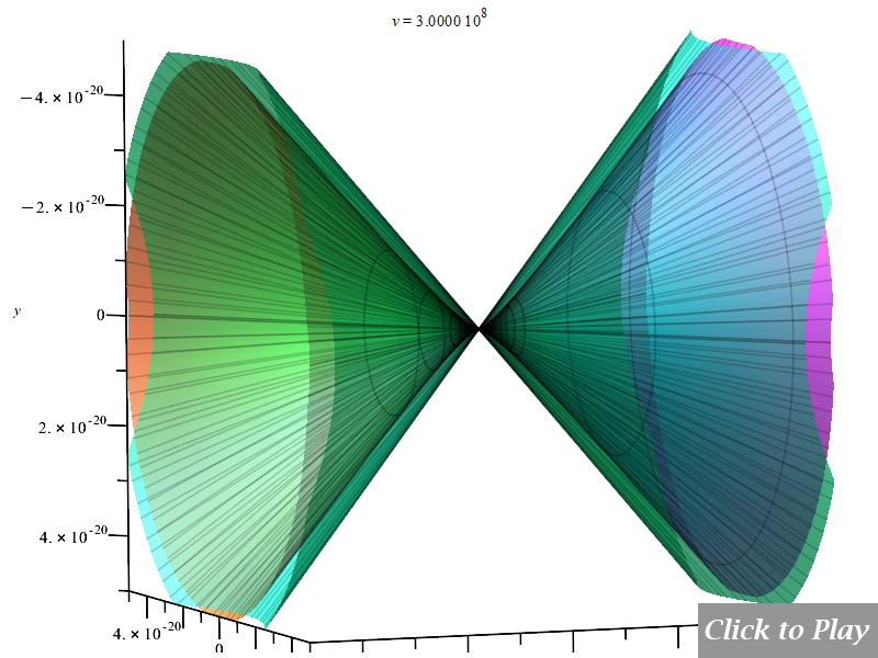
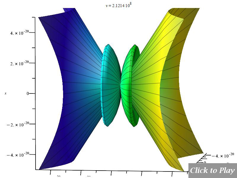
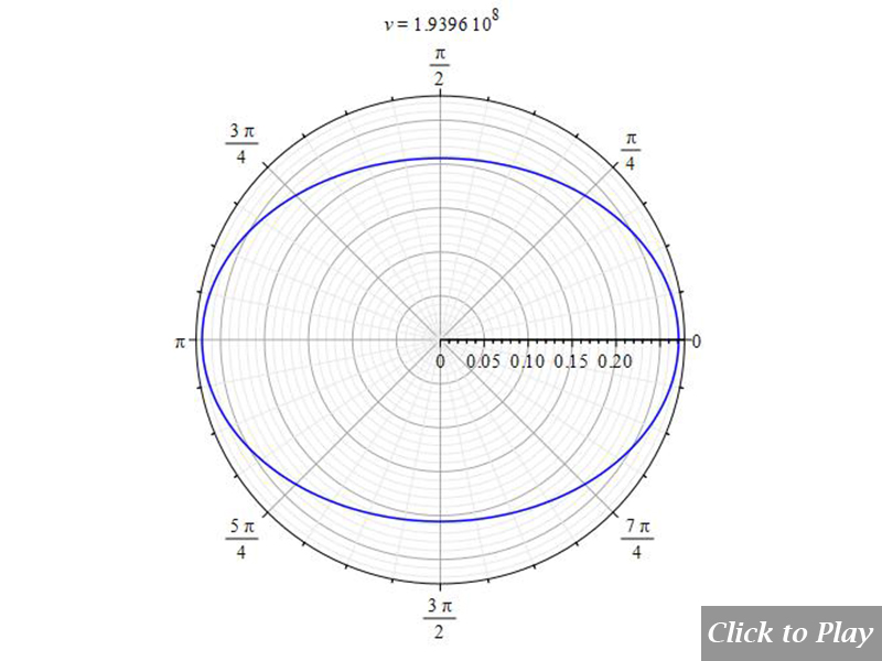
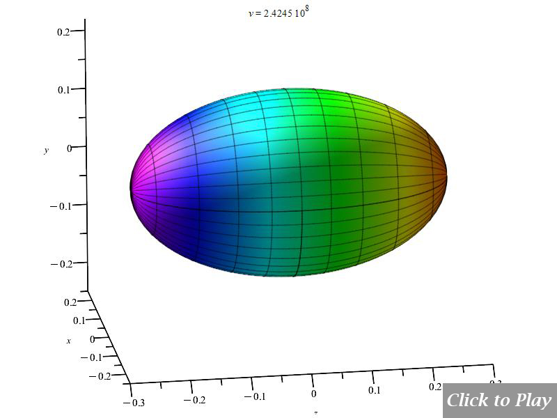
Figs. 10 and 11 clearly show how the radiation wavefront perpendicular to the motion breaks off in a shock wave radiation cone when the charge speed exceeds the radiation speed limit. As charge velocity rises, the radiation cone’s aperture shrinks.
Note that because of scale, part of the radiation cone may be cut at the 3D box limits.
The “searchlight” effect given by Eq. (11e) does not satisfy the Cherenkov effect
We have already stated at the beginning of this section that the pattern given by Eq. (11e) does not obey the Cherenkov effect, as can be seen in Figs. 12 and 13. For simplicity, a value of one was given to K and a in Eq. (11e).
According to Eq. (5a), the pattern must decrease the aperture of the wavefront as velocity increases. Here happens the opposite!
Figures 12 and 13 show the result of Eq. (11e). It is evident that such an equation, which is widely spread in scientific papers, is not in agreement with the Cherenkov effect, and therefore, it should be assumed to be wrong.
Charge Radiation in Uniform Circular Motion
We assume that the circular motion is in the x-y plane of the spherical coordinate system. Since the angular velocity is constant, we have the following expressions for velocity and acceleration:
\vec{v}=r\dot{\phi}\hat{\phi}\left(t\right) and \vec{a}=-r{\dot{\phi}}^2\hat{r}
Polar graphs for charge radiation in uniform circular motion
Equations of motion in spherical coordinates (12) to (14) and angle (15) are replaced in Eq. (8), and the following parameters were set for the polar graphs in figures 14, 15, 16, and 17:
| q_1=q_2={1.6\ 10}^{-19} | r\left(t\right)=see\ graphs | {\dot{r}}(t)={\dot{\phi}}(t)\cdot r (t) | \ddot{r}\left(t\right)=0 |
| \dot{\theta}\left(t\right)=0 | \ddot{\theta}\left(t\right)=0 | {\dot{\phi}}(t)=\frac{v}{r (t)} | \ddot{\phi}\left(t\right)=0 |
| \frac{d}{dt}\left(\ddot{r}\left(t\right)\right)=0 | \frac{d}{dt}\left(\ddot{\theta}\left(t\right)\right)=0 | \frac{d}{dt}\left(\ddot{\phi}\left(t\right)\right)=0 |
The horizontal axis represents velocity. Notable intensity shifts were caused by changes in relative distance.
Jitter does not apply in this motion
There is no jitter in this type of motion because we have zero linear acceleration and constant angular acceleration.
The Cherenkov effect in uniform circular motion
Equations of motion in spherical coordinates (12) to (14) and angle (15) are replaced in Eq. (8), and the following parameters were set for the polar graphs in Figs. 18 and 19:
| q_1=q_2={1.6\ 10}^{-19} | r\left(t\right)=see\ graphs | {\dot{r}}(t)={\dot{\phi}}(t)\cdot r (t) | \ddot{r}\left(t\right)=0 |
| \dot{\theta}\left(t\right)=0 | \ddot{\theta}\left(t\right)=0 | {\dot{\phi}}(t)=\frac{v}{r (t)} | \ddot{\phi}\left(t\right)=0 |
| \frac{d}{dt}\left(\ddot{r}\left(t\right)\right)=0 | \frac{d}{dt}\left(\ddot{\theta}\left(t\right)\right)=0 | \frac{d}{dt}\left(\ddot{\phi}\left(t\right)\right)=0 | c=2.25\ {10}^8 |
Keep in mind that scaling may cause the radiation cone to be truncated at the 3D box boundaries.
Charge Radiation in Non-Uniform Circular Motion
We assume that the circular motion is in the x-y plane of the spherical coordinate system. Since the angular velocity and angular acceleration are not constant, we have the following expressions for velocity and acceleration:
{\vec{v}}=r {\dot{\phi}} \hat{\phi}(t) and \vec{a}=-r{\dot{\phi}}^2\hat{r}+r\ddot{\phi}\left(t\right)\hat{\phi}\left(t\right)
Polar graphs for charge radiation in non-uniform circular motion
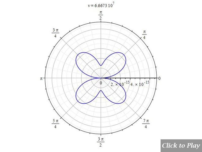
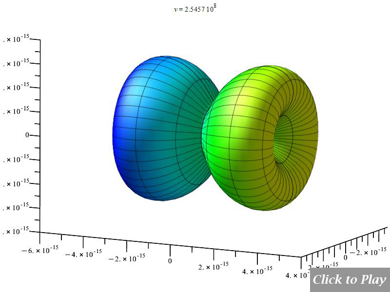
Equations of motion in spherical coordinates (12) to (14) and angle (15) are replaced in Eq. (8), and the following parameters were set for the polar graphs in figures 20, 21, 22, and 23:
| q_1=q_2={1.6\ 10}^{-19} | r\left(t\right)=see\ graphs | {\dot{r}}(t)={\dot{\phi}}(t)\cdot r (t) | \ddot{r}\left(t\right)=0 |
| \dot{\theta}\left(t\right)=0 | \ddot{\theta}\left(t\right)=0 | {\dot{\phi}}(t)=\frac{v}{r (t)} | \ddot{\phi}\left(t\right)=1 |
| \frac{d}{dt}\left(\ddot{r}\left(t\right)\right)=0 | \frac{d}{dt}\left(\ddot{\theta}\left(t\right)\right)=0 | \frac{d}{dt}\left(\ddot{\phi}\left(t\right)\right)=0 |
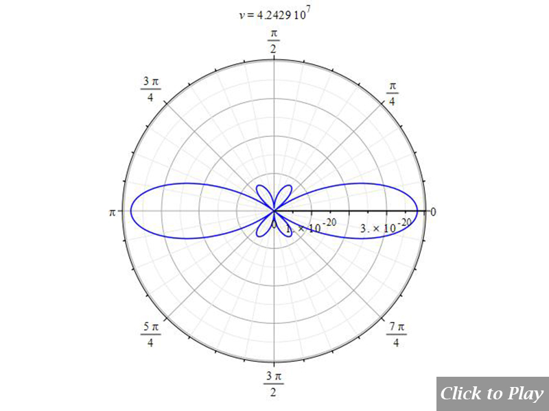
The horizontal axis represents velocity, while the vertical axis represents centripetal acceleration. Observe the reduction in radiation power as relative distance increases.
For higher angular acceleration:
Equations of motion in spherical coordinates (12) to (14) and angle (15) are replaced in Eq. (8), and the following parameters were set for the polar graphs in Figs. 24 and 25:
| q_1=q_2={1.6\ 10}^{-19} | r\left(t\right)=see\ graphs | {\dot{r}}(t)={\dot{\phi}}(t)\cdot r (t) | \ddot{r}\left(t\right)=0 |
| \dot{\theta}\left(t\right)=0 | \ddot{\theta}\left(t\right)=0 | {\dot{\phi}}(t)=\frac{v}{r (t)} | \ddot{\phi}\left(t\right)={10}^{18} |
| \frac{d}{dt}\left(\ddot{r}\left(t\right)\right)=0 | \frac{d}{dt}\left(\ddot{\theta}\left(t\right)\right)=0 | \frac{d}{dt}\left(\ddot{\phi}\left(t\right)\right)=0 |
Example considering jitter in non-uniform circular motion
Equations of motion in spherical coordinates (12) to (14) and angle (15) are replaced in Eq. (8), and the following parameters were set for the polar graphs in Figs. 26 and 27:
| q_1=q_2={1.6\ 10}^{-19} | r\left(t\right)=see\ graphs | {\dot{r}}(t)={\dot{\phi}}(t)\cdot r (t) | \ddot{r}\left(t\right)=0 |
| \dot{\theta}\left(t\right)=0 | \ddot{\theta}\left(t\right)=0 | {\dot{\phi}}(t)=\frac{v}{r (t)} | \ddot{\phi}\left(t\right)={10}^{15} |
| \frac{d}{dt}\left(\ddot{r}\left(t\right)\right)=0 | \frac{d}{dt}\left(\ddot{\theta}\left(t\right)\right)=0 | \frac{d}{dt}\left(\ddot{\phi}\left(t\right)\right)={10}^{20} |
The smaller lobes show a modest reduction in the direction of acceleration, but the radiation strength increases in the direction of velocity.
The Cherenkov effect in non-uniform circular motion
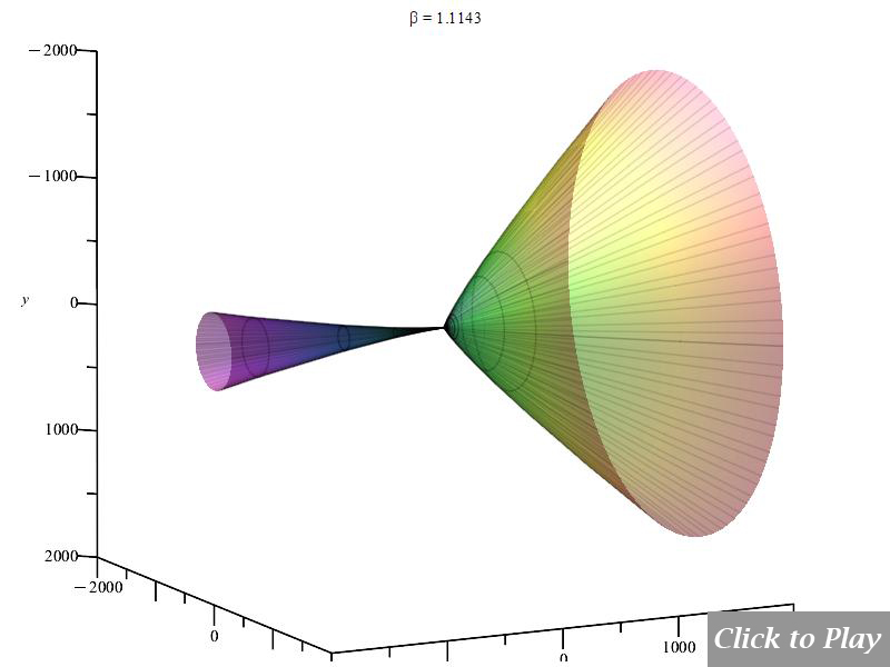
Equations of motion in spherical coordinates (12) to (14) and angle (15) are replaced in Eq. (8), and the following parameters were set for the polar graphs in Figs. 28, 29, 30, and 31:
| q_1=q_2={1.6\ 10}^{-19} | r\left(t\right)=see\ graphs | {\dot{r}}(t)={\dot{\phi}}(t)\cdot r (t) | \ddot{r}\left(t\right)=0 |
| \dot{\theta}\left(t\right)=0 | \ddot{\theta}\left(t\right)=0 | {\dot{\phi}}(t)=\frac{v}{r (t)} | \ddot{\phi}\left(t\right)={10}^{15} |
| \frac{d}{dt}\left(\ddot{r}\left(t\right)\right)=0 | \frac{d}{dt}\left(\ddot{\theta}\left(t\right)\right)=0 | \frac{d}{dt}\left(\ddot{\phi}\left(t\right)\right)=0 | c=2.25\ {10}^8 |
Keep in mind that scaling might result in the radiation cone cutting at the edges of the 3D box.
Radiation from Charge for an Arbitrary Motion
We assume an arbitrary spatial motion with acceleration components in all directions.
Polar graphs of charge radiation for an arbitrary motion
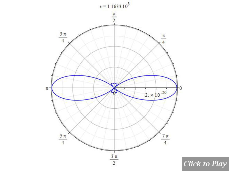
Equations of motion in spherical coordinates (12) to (14) and angle (15) are replaced in Eq. (8), and the following parameters were set for the polar graphs in figures 32, 33, 34, 35, 36, and 37:
| q_1=q_2={1.6\ 10}^{-19} | r\left(t\right)=see\ graphs | \dot{r}\left(t\right)=v | \ddot{r}\left(t\right)=10 |
| \dot{\theta}\left(t\right)={10}^{6} | \ddot{\theta}\left(t\right)={2\ 10}^{19} | \dot{\phi}\left(t\right)={5\ 10}^{6} | \ddot{\phi}\left(t\right)={10}^{20} |
| \frac{d}{dt}\left(\ddot{r}\left(t\right)\right)=0 | \frac{d}{dt}\left(\ddot{\theta}\left(t\right)\right)=0 | \frac{d}{dt}\left(\ddot{\phi}\left(t\right)\right)=0 |
Velocity is acceptable in any direction. The scale of Figs. 36 and 37 is interatomic. Take note of the fact that the radiation rises and peaks at a certain velocity and falls at higher velocities.
Example considering jitter in an arbitrary motion
Equations of motion in spherical coordinates (12) to (14) and angle (15) are replaced in Eq. (8), and the following parameters were set for the polar graphs in Figs. 38 and 39:
| q_1=q_2={1.6\ 10}^{-19} | r\left(t\right)=see\ graphs | \dot{r}\left(t\right)=v | \ddot{r}\left(t\right)=10 |
| \dot{\theta}\left(t\right)={10}^{6} | \ddot{\theta}\left(t\right)={2\ 10}^{19} | \dot{\phi}\left(t\right)={5\ 10}^{6} | \ddot{\phi}\left(t\right)={10}^{20} |
| \frac{d}{dt}\left(\ddot{r}\left(t\right)\right)={10}^{36} | \frac{d}{dt}\left(\ddot{\theta}\left(t\right)\right)={9\ 10}^{33} | \frac{d}{dt}\left(\ddot{\phi}\left(t\right)\right)={10}^{32} |
Centripetal acceleration is mostly found in the vertical axis, whereas velocity is primarily found in the horizontal axis. In general, the radiation power is increased in all directions by jitter.
The Cherenkov effect in an arbitrary motion
Equations of motion in spherical coordinates (12) to (14) and angle (15) are replaced in Eq. (8), and the following parameters were set for the polar graphs in Figs. 40, and 41:
| q_1=q_2={1.6\ 10}^{-19} | r\left(t\right)=see\ graphs | \dot{r}\left(t\right)=v | \ddot{r}\left(t\right)=10 |
| \dot{\theta}\left(t\right)={10}^{6} | \ddot{\theta}\left(t\right)={2\ 10}^{19} | \dot{\phi}\left(t\right)={5\ 10}^{6} | \ddot{\phi}\left(t\right)={10}^{20} |
| \frac{d}{dt}\left(\ddot{r}\left(t\right)\right)=0 | \frac{d}{dt}\left(\ddot{\theta}\left(t\right)\right)=0 | \frac{d}{dt}\left(\ddot{\phi}\left(t\right)\right)=0 |
Keep in mind that scaling may cause the radiation cone to cut at the 3D box’s boundaries.
Conclusions
Relative motion depends on relative coordinates, not on reference frames. The same motion results will be measured in any frame of reference. Physics has lost more than 100 years of evolution because of a wrong and unfortunate theory elaborated by Einstein.
A comprehensive spatial power radiation equation has been obtained from the total energy of the system of charges. The spatial radiation power equation contains jitter terms, which are totally absent in other published works.
The base of our spatial power radiation and total energy equations is the Universal Electrodynamic Force, from which they were derived. This universal force is valid on any scale.
The derived spatial power radiation equation proves the Cherenkov effect.
It has been demonstrated the real radiation pattern from the real relative motion of charges for some typical motions.
The widely used equation 11e in scientific literature, which demonstrates the radiation “searchlight” effect, was shown to be incompatible with the Cherenkov effect.
Bibliography
[1]. Joseph Larmor, “A Dynamical Theory of the Electric and Luminiferous Medium.—Part III. Relations with Material Media”, (1897), https://royalsocietypublishing.org/doi/epdf/10.1098/rsta.1897.0020
[2]. Raul Fattore, “Negative Mass and Negative Refractive Index in Atom Nuclei – Nuclear Wave Equation – Gravitational and Inertial Control” (2023), Part-1, Part-2, Part-3, Part-4, Part-5, Part-6
[3]. Raul Fattore, “Nuclear Fusion Enhanced by Negative Mass – A Proposed Method and Device” (2024), Part 1
[4]. Raul Fattore, “Nuclear Fusion Enhanced by Negative Mass – A Proposed Method and Device” (2024), Part 2
[5]. Raul Fattore, “Nuclear Fusion Enhanced by Negative Mass – A Proposed Method and Device” (2024), Part 3
[6]. Raul Fattore, “What is Charge? – The Redefinition of Atom – Energy to Matter Conversion” (2023), https://physics-answers.com/what-is-charge-the-redefinition-of-atom-energy-to-matter-conversion/
[7]. Mert Yücemöz, Martin Füllekrug, “Asymmetric Backward Peaking Radiation Pattern From a Relativistic Particle Accelerated by Lightning Leader Tip Electric Field” (2021), https://agupubs.onlinelibrary.wiley.com/doi/full/10.1029/2020JD033204
Related articles:
Nuclear Fusion Enhanced by Negative Mass – A Proposed Method and Device – (Part 1)
Nuclear Fusion Enhanced by Negative Mass – A Proposed Method and Device – (Part 2)
Nuclear Fusion Enhanced by Negative Mass – A Proposed Method and Device – (Part 3)
Nuclear Fusion Enhanced by Negative Mass – A Proposed Method and Device – (Part 4)
What is Charge? – The Redefinition of Atom – Energy to Matter Conversion
Faster-Than-Light Travel Feasible with Negative Mass – Superluminal Dynamics
New Atomic Model with Real-Valued Wave Function – Energy Levels, Spectrum, and Atomic Fine Structure
